Developing the ATLAS End-Cap Toroids: a personal history
26 January 2022 | By
In this blog post, former ATLAS engineer Elwyn Baynham shares his experience as part of the team developing the ATLAS End-Cap Toroids. His story paints a personal picture of the history of these incredible magnets.
My journey began in 1970, when I joined the Superconductivity Group at the Rutherford Appleton Laboratory (RAL) in the UK. At the time, the group was creating prototype accelerator dipole magnets aimed at a future superconducting accelerator. The Super Proton Synchrotron (SPS) was seen as a possible candidate for these magnets, but ultimately CERN decided to use conventional copper magnets. Despite this disappointment, RAL’s development programme yielded two important pieces of technology that would play a major role in future applications of superconductivity: filamentary superconducting wires, which are the basis of almost every superconducting magnet, and Rutherford cables, the conductor used in all superconducting accelerator magnets including those at the Large Hadron Collider (LHC).

By the 80s, particle colliders had evolved to require large magnetic fields around their interaction points and large superconducting solenoids were being developed for this application. My colleagues at RAL designed and built the superconducting solenoid for the DELPHI experiment at CERN’s Large Electron–Positron (LEP) collider. It arrived at CERN in 1987, measuring approximately 5m in diameter and 5m in length – the world’s largest superconducting solenoid magnet at the time. While small by modern standards, DELPHI’s magnet was already at the limit of what could be transported to CERN (see Figure 1).
Magnet systems for the LHC experiments were already being discussed by the early 90s. My involvement in this began in 1992, working with members of RAL’s particle physics department to understand what type of magnets would be required and also what sort of magnet technology would be feasible. This was an exciting time to get involved – before the ATLAS Collaboration was even officially formed and named.
Designing the magnets
By 1997, ATLAS’ huge toroidal magnet system was fully defined, with the RAL team taking responsibility for the design and manufacture of the End-Cap Toroids. There were many design challenges, not least the size. Although small compared with the Barrel Toroid, the End Caps were at least twice the size of any previous detector magnet: approximately ten metres in diameter and five metres in length. This meant that the magnets could not be transported as a complete assembly and the design had to factor in a final assembly at CERN. Although very different from the detector solenoids of LEP, two pieces of technology developed for those magnets were key to the ATLAS design: indirect cooling of the superconducting coils using a helium coolant circulated in pipes, and superconducting cables stabilised and protected by high-purity aluminium.

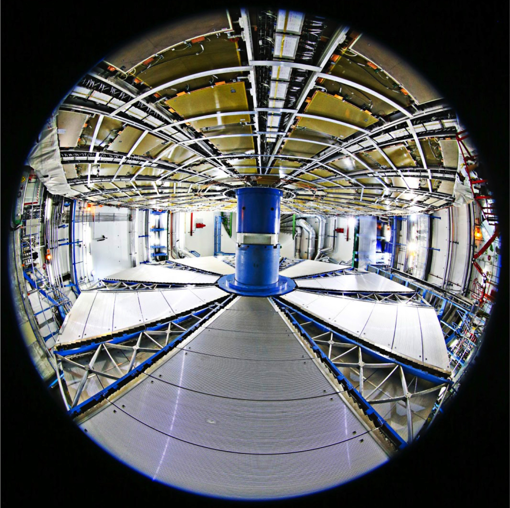
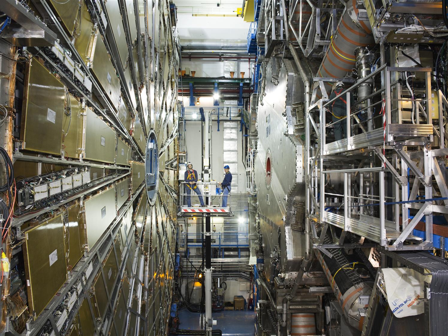
The End-Cap Toroids provide a magnetic field for muon detection at the two ends of the cylindrical detector, around the beam pipe. Each End Cap consists of eight superconducting pancake coils (see Figures 3 and 4) mounted as a single cold mass to form the toroidal structure. Its design was closely integrated with that of the Barrel Toroid, both in terms of detector performance and magnetic forces. To achieve the maximum magnetic field with which to bend the paths of muons, the End-Cap coils interleave with the Barrel Toroid coils in the radial direction, like gear wheels. This led to the grooved design of the End-Cap Cryostat structure, as shown in Figure 2.
When designing ATLAS’ superconducting magnet system, we had to carefully consider ways to protect the superconducting winding in the event of a magnet “quench”, where part of the winding overheats and brings the magnet from superconducting to the normal resistive state. This was an issue for the End Caps as well as the Barrel Toroid.
The magnetic energy stored in two End Caps is 400 Megajoules. If a normal resistive zone begins in any part of the winding, this stored energy must be dissipated rapidly, either externally or over the whole winding. If not, it could locally burn out the conductor at the quench origin. In the ATLAS toroids, Barrel and End Caps, this protection is achieved through heaters in each coil to dissipate the energy over every coil and thereby reduce the maximum temperature at the initial fault to an acceptable level.

Making the dream a reality
The next step was to manufacture these huge coils and vessels; this process began in 1999. The manufacturing was done mainly as in-kind contributions from member institutes of ATLAS. In particular, the cold mass and the vacuum vessel were manufactured under NIKHEF (the Netherlands), with the RAL team responsible for the initial specification and technical monitoring of the contracts. The overall process was managed by a CERN team led by Herman ten Kate. A similar arrangement was used for the thermal radiation shields, which were manufactured in Israel.
The transport of the vacuum vessels was a major factor in the design. In 2002, the vessels were transported in halves, partly by barge and finally by road. Just one half of the vessel was already at the extreme limit for road transport, as shown in Figure 10.

The assembly of the components at CERN was carried out by the CERN team, and supported by a team of engineers and technicians from Dubna in the USSR. The assembly was carried out mainly in Buildings 180 and 191 at CERN (see Figure 12). The half vacuum vessels were assembled and vacuum tested after the final welding operations. Thermal shields and super-insulation were installed in the vacuum vessel. The cold mass parts were assembled and the internal cooling circuits installed.
The final operation was to integrate the cold mass with the vacuum vessel. This was a delicate operation with two structures ten metres in diameter and only 25 to 50 millimetres clearance. The cold mass was supported on a cantilever and the vessel shell moved over it on a rail system as shown in Figure 8. Before closure of the end plates, the service turret was connected. This turret couples all the services, coolant, electrical power and instrumentation/control sensors to the exterior.
The End-Cap Toroids are probably unique for such big magnets as they were required to be movable with the cold mass at cryogenic temperature. To allow access to the inner part of the detector, the End Caps must be withdrawn along the beam axis some five metres and then transferred sideways approximately ten metres as illustrated in Figure 9. This is achieved by an umbilical system of cryo-lines, electrical cables, vacuum and instrumentation cables mounted in a massive chain-like structure at the top of the ATLAS Barrel Toroid. The chain structure is flexible in the horizontal plane but very stiff in the vertical direction which allows it to span the large gaps, greater than 10 m, without support.


Transporting a giant
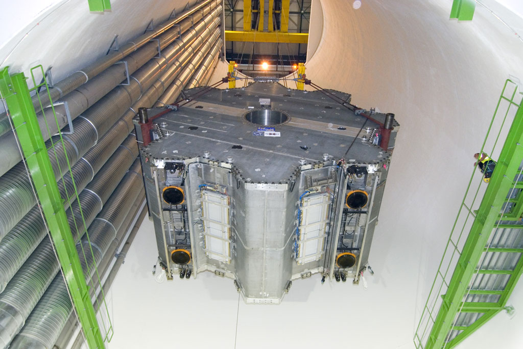
The completed End Caps were transported across the CERN site to the ATLAS surface building SX1. Figures 14 and 15 give an impression of the scale. Special tooling was required first to transfer the magnet into the surface building and to lower it partly down the shaft where the load was transferred to the crane for the final descent into the cavern.
Each End-Cap Toroid was commissioned separately in the cavern before the final powering of the complete ATLAS toroid magnet system. Final commissioning took place over three days, 16–18 August 2008. The full magnet system was operated with its design field to demonstrate its readiness for the experiment to enter its operational phase. Those commissioning tests were the culmination of some 14 years of work by engineering teams from a number of European laboratories in collaboration with the physicists of the ATLAS Collaboration and the CERN magnet team. For me, it was my last major project and time for retirement.


