Successful mapping of the solenoid magnet
5 October 2006 | By

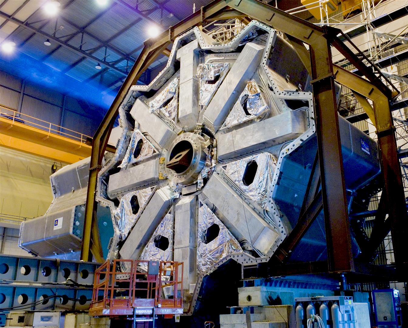
The ATLAS solenoid coil is about 5.3m long, has a diameter of 2.5m and is designed to deliver a magnetic field of approximately 2T for the ATLAS inner detector. The superconducting solenoid coil has been integrated inside the LAr barrel cryostat and was installed at its final position inside the cavern in November 2005. This summer - after completion of the extended barrel calorimeters and before the installation of the inner detector - the end cap calorimeters (LAr end caps and Tile extended barrels) were moved for the first time into their final position in order to create conditions as close as possible to final for the solenoid tests and for mapping the field inside the solenoid bore.
Design and construction of the mapping machine
The requirement on the absolute precision of the field measurements are 0.05% on the field integrals seen by particles; if this is achieved the momentum error coming from insufficient knowledge of the magnetic field will be negligible compared to the error stemming from the inner detector alignment. This requirement on the field precision translates into stringent requirements on the precision of the mechanics of the mapping machine and the survey (~0.5mm).
A dedicated mapping machine was designed and constructed by the CERN PH/DT1 group in close collaboration with ATLAS. Besides the stringent requirements on the precision it was the fact that the machine was not accessible during the mapping campaign which made this task challenging. A machine was built consisting of an aluminum traverse system moving along the beam axis on the inner detector V-rails, and two propeller arms with an angle of 90 degrees sweeping the solenoid volume in phi. On these propeller arms 48 previously calibrated Hall probes were mounted. As a propulsion system non-magnetic pneumatic motors were chosen whose force was transmitted to the wheels and the rotating propeller arms by non-magnetic gear systems and belts. Encoders monitored the exact position in phi and in z (on both rails independently) and gave feedback to the pneumatic motors to minimize the skew of the machine and to stop as close as possible to the demanded positions.
The mapping campaign
After the final in situ commissioning of the solenoid itself the mapping campaign started on August 2 and lasted until August 7. The solenoid field was mapped during all together 50 hours by moving the machine in z and then at each z-position rotating the propeller arms in 16 steps by 360 degrees. At each step the currents and temperatures of the Hall probes were read out and written to disk. The mapping machine movement and data acquisition were controlled by our test rack that was installed on the ground floor of the UX15 cavern. Dedicated online monitoring software made it possible to check the measured data immediately after reading them. At nominal field (approximately 2T in the solenoid center at a solenoid current of 7730A) 139000 data points were taken, corresponding to in average 6 field measurements in each cubic decimeter of the solenoid volume. The following runs were recorded:
- Scans where the 4 Hall probe planes on the propeller arms overlap at the solenoid center and at the solenoid end in order to extract the angles of individual Hall probes on the mapper arms and correct for them.
- Many scans over the whole solenoid length and beyond from z=-2.93cm (C-side) to z=2.99cm (A-side).
- Special fine scans of the coil ends for the extraction of the exact position of the coil ends, fine scans in phi at the center of the solenoid to measure the position of the return conductor, and fine scans in z at the center to investigate the exact shape of the field distortion due to the welds between solenoid pieces.
Similar measurements were taken for 7850A (maximum current), 7000A and 5000A. The mapping campaign worked smoothly and was finished successfully in a shorter time than previously foreseen.
Preliminary results
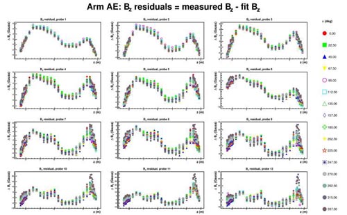
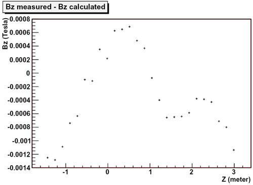
Approximately one month after the mapping campaign only parts of the data have been looked at. The initial emphasis has been on understanding the performance of the mapping machine. Preliminary results show that the difference between the nominal calculated field maps (global ATLAS field map) including the TileCal iron contribution and the measured data is of the order of 20 Gauss. The integration of the survey data into the data reconstruction, correcting for small angular mis-alignments of individual Hall probes and fitting the shape and position of the solenoid coil, this difference has been reduced to an r.m.s. of 7.6 Gauss. (For these fits the iron contribution is described by 4 terms of a Fourier-Bessel series.) The plot below shows the fit residuals of the Bz component (5000 A data) for all the Hall probes on one mapper arm. The best fit position of the solenoid coil center (2.3mm lower than the cryostat axis) agrees well with survey measurements performed during the integration of the solenoid coils into the LAr cryostat.
We are very confident that with a further, more refined analysis the required accuracy of the prediction of the field integrals of 0.05% will be achieved.
I want to thank all the people who contributed to the solenoid field measurements and made this mapping campaign a success.


