ATLAS Update and Blog Authors


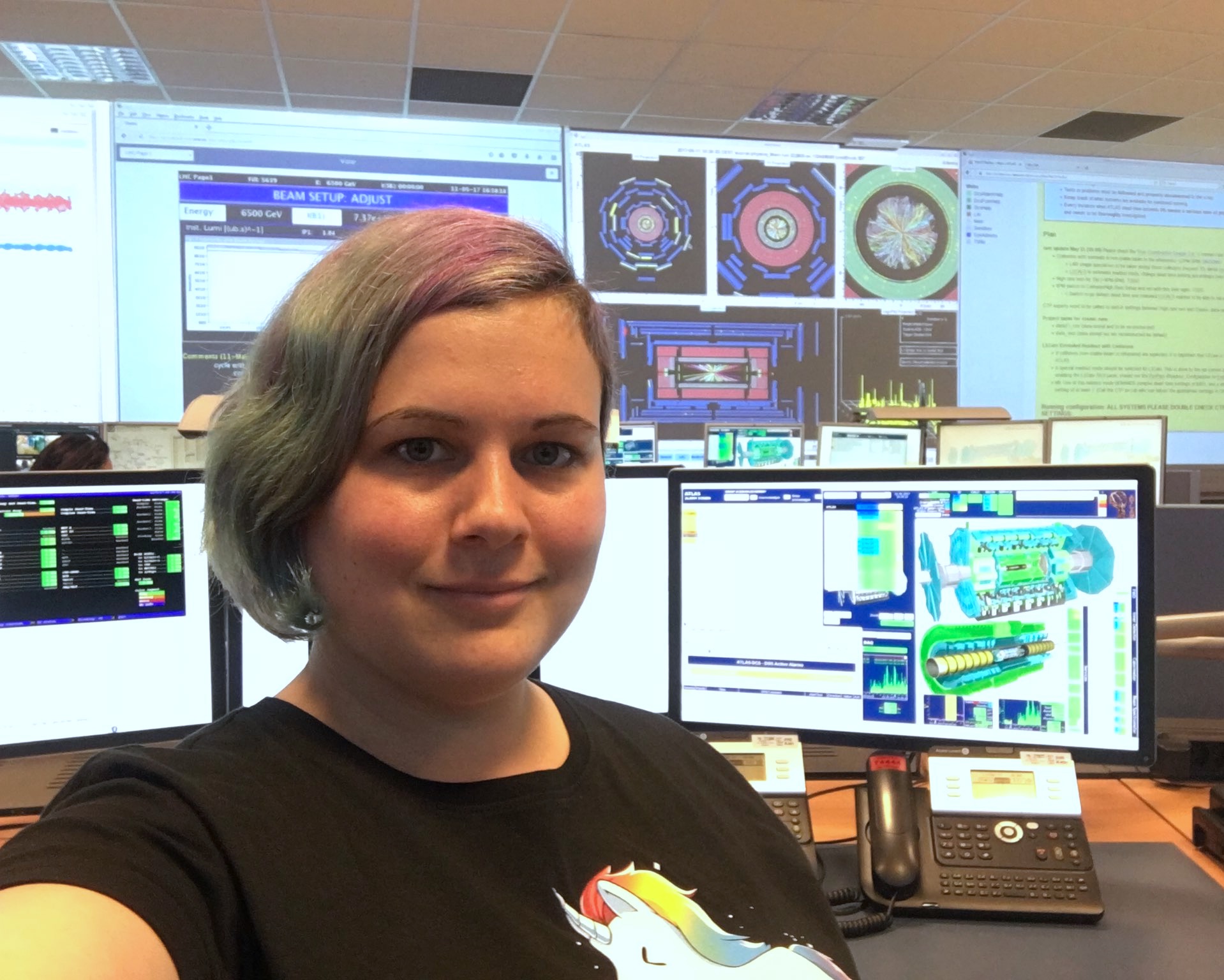


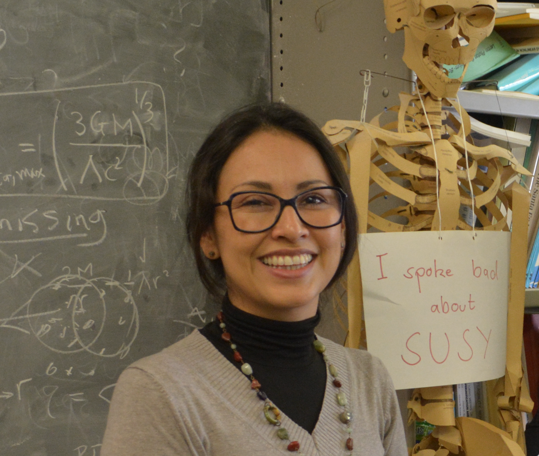

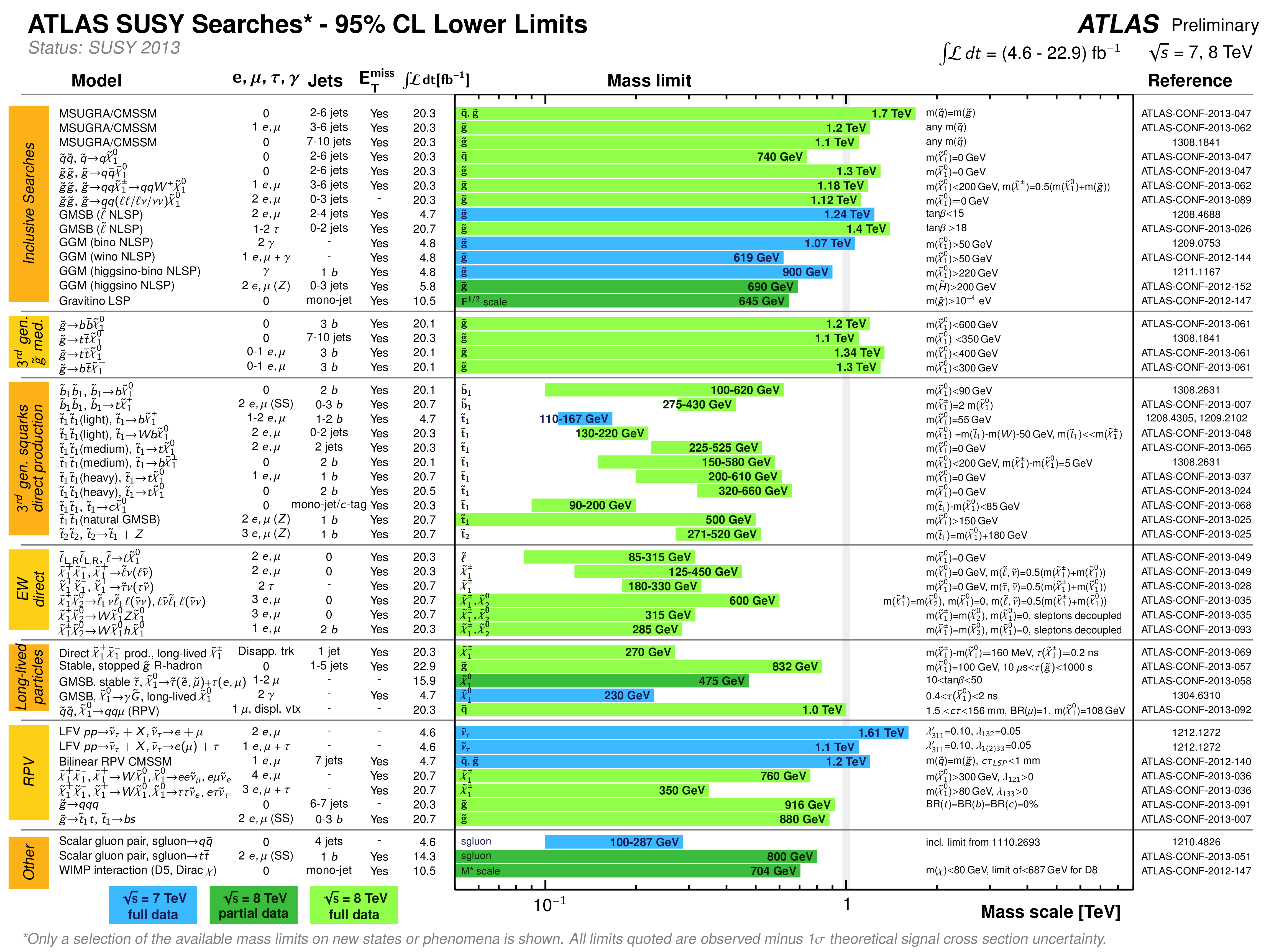
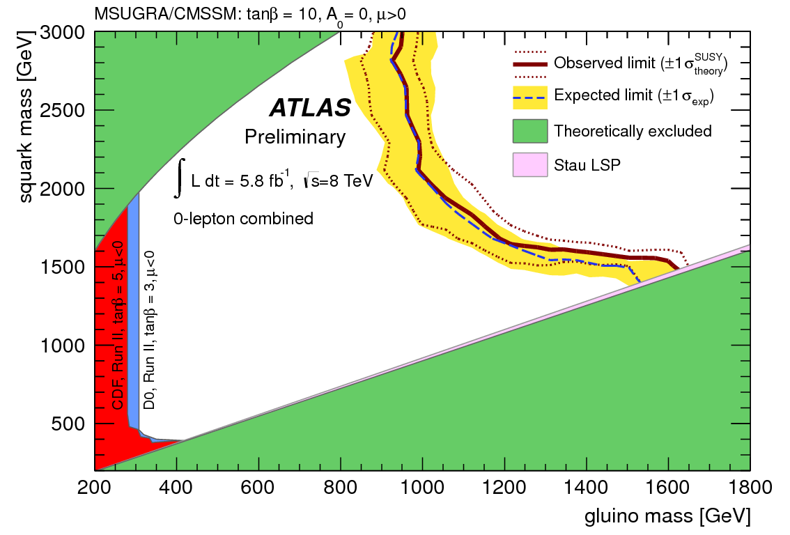
So where is all the SUSY?
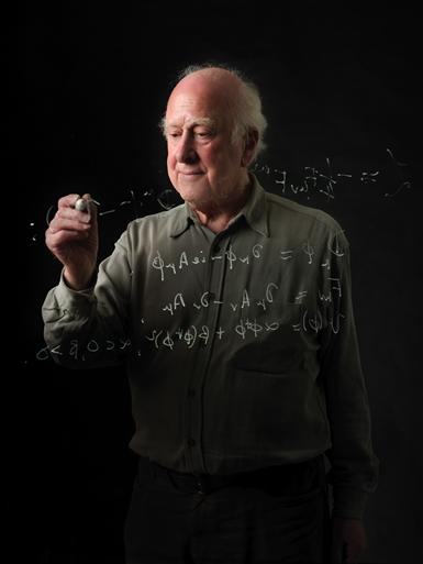
Supersymmetry (SUSY) is one of the most loved, and most hated, theories around that works as an extension of our beloved Standard Model.
Blog |
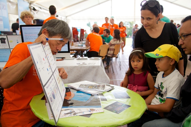
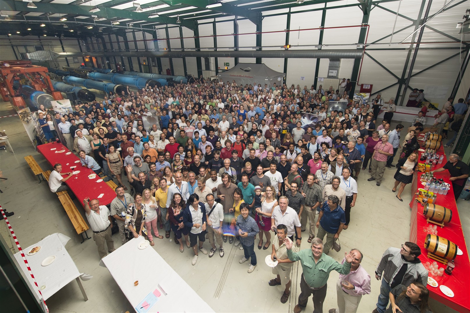
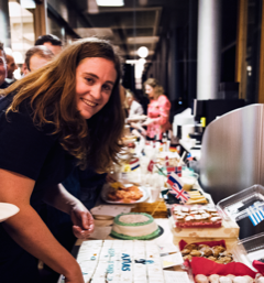
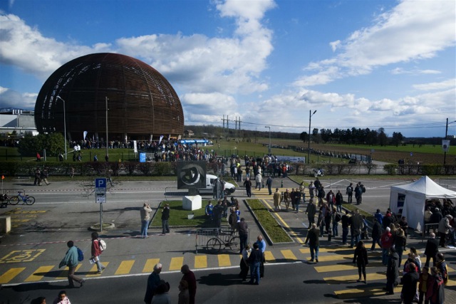
Crowds at ATLAS for CERN Open Days
More than 70,000 people visited CERN Open Days over the weekend, with 20,000 going underground to see the LHC tunnel and the detectors. Of these, an estimated 5,000 people visited the ATLAS exhibits aboveground, and another 2,500 had the opportunity to see the ATLAS detector.
News |
Sharing the excitement of discovery
Only a few more days to go before CERN opens its doors and our universe becomes yours on 28 and 29 September. With 35 surface sites and seven underground visits available, there will be plenty of activities for visitors of all ages.
News |
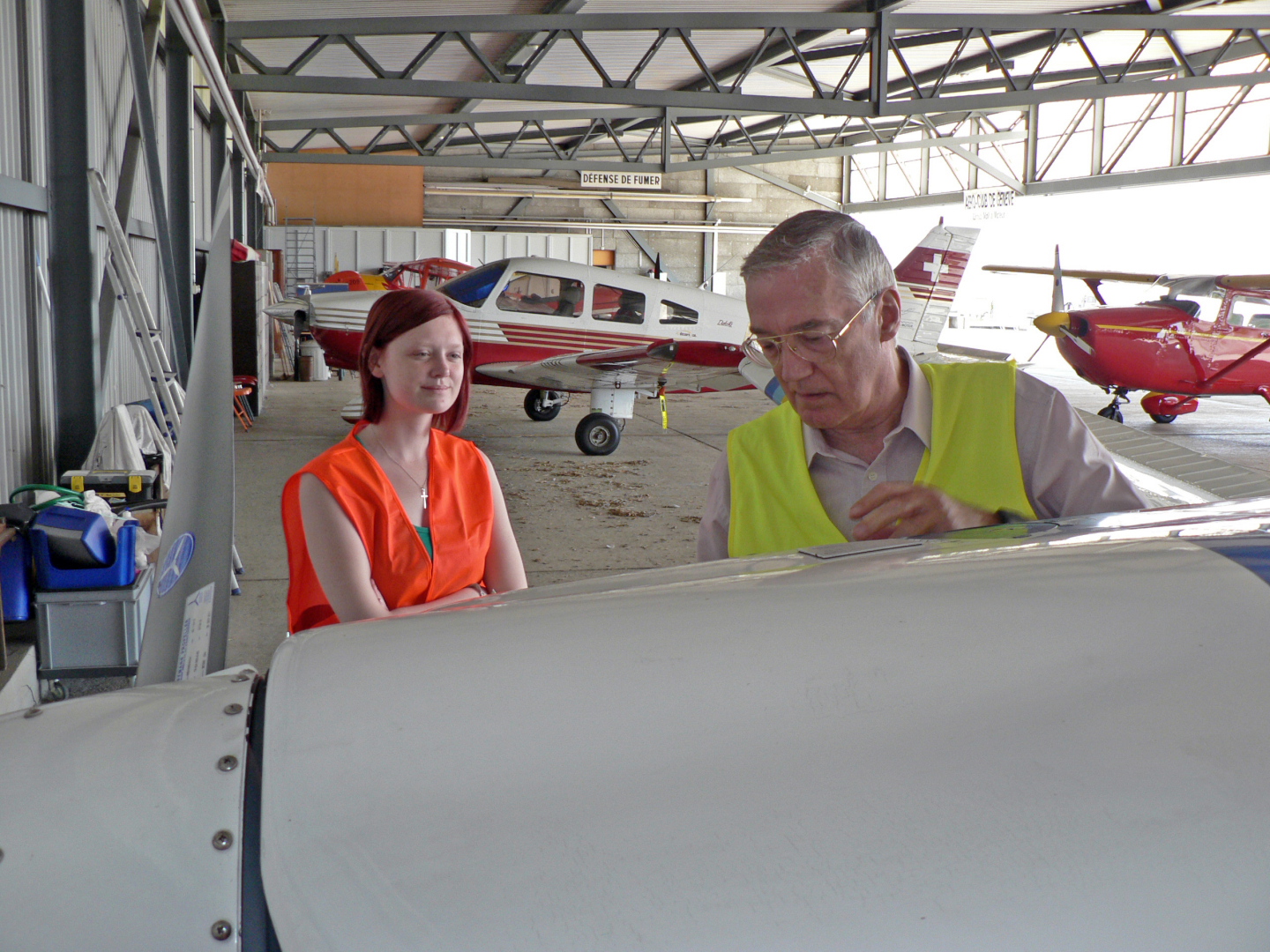
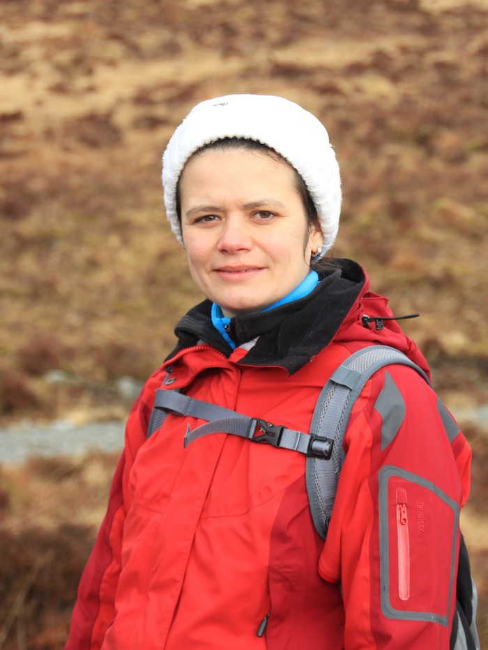
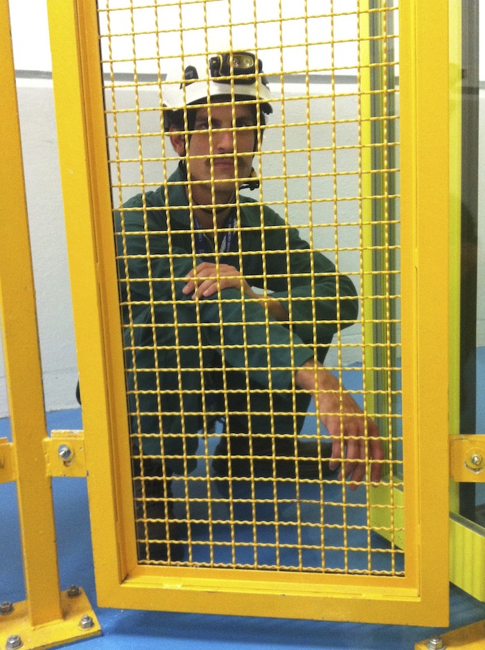
High-flying physics
Pernilla Craig earned her licence to fly last year aged just 17, making her one of UK’s youngest female pilots. A visit to CERN last week took her deep underground to see dectectors on the Large Hadron Collider (LHC), and into the sky above the Alps for a bird's eye view of the laboratory.
News |
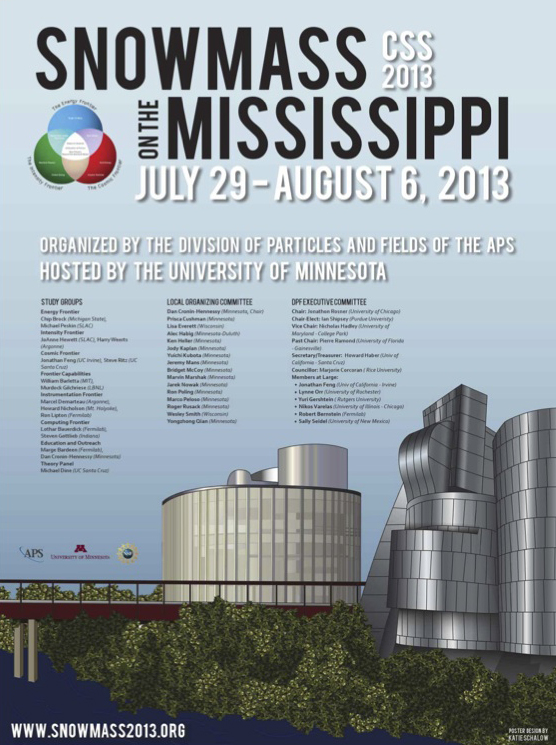
Snowmass from Afar
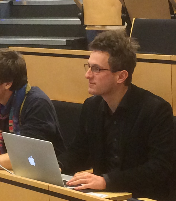
There's a (potentially) really big deal in physics that's just ended: the Snowmass conference. Ken over at the USLHC blog has already mentioned it, and I've been watching with interest from here in Geneva as well. The meeting, and its reports, are trying to walk an extrodinarily delicate line that's interesting for both the physics and the sociology involved.
Blog |
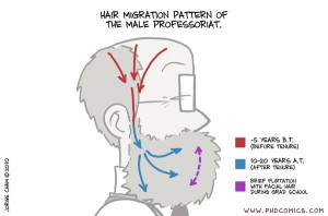
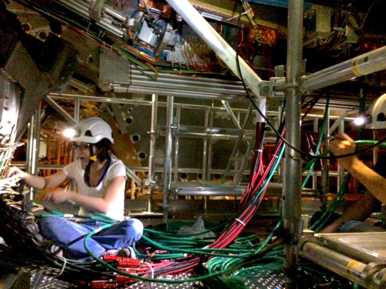
A Few Missing Steps
After a long hiatus from US ATLAS, I recently started a new job at the Lawrence Berkeley National Laboratories. It's one of the few remaining labs in the US funded by the Department of Energy that does basic science research. It's the fourth job I've had in four years, all working on ATLAS, and all working on similar projects. This one is different, though: if I pass a performance review a few years from now, I'll have the lab-equivalent of tenure. I've had reactions ranging from "who did you have to kill to get that job" to "so who did you actually talk to to land that"?
Blog |
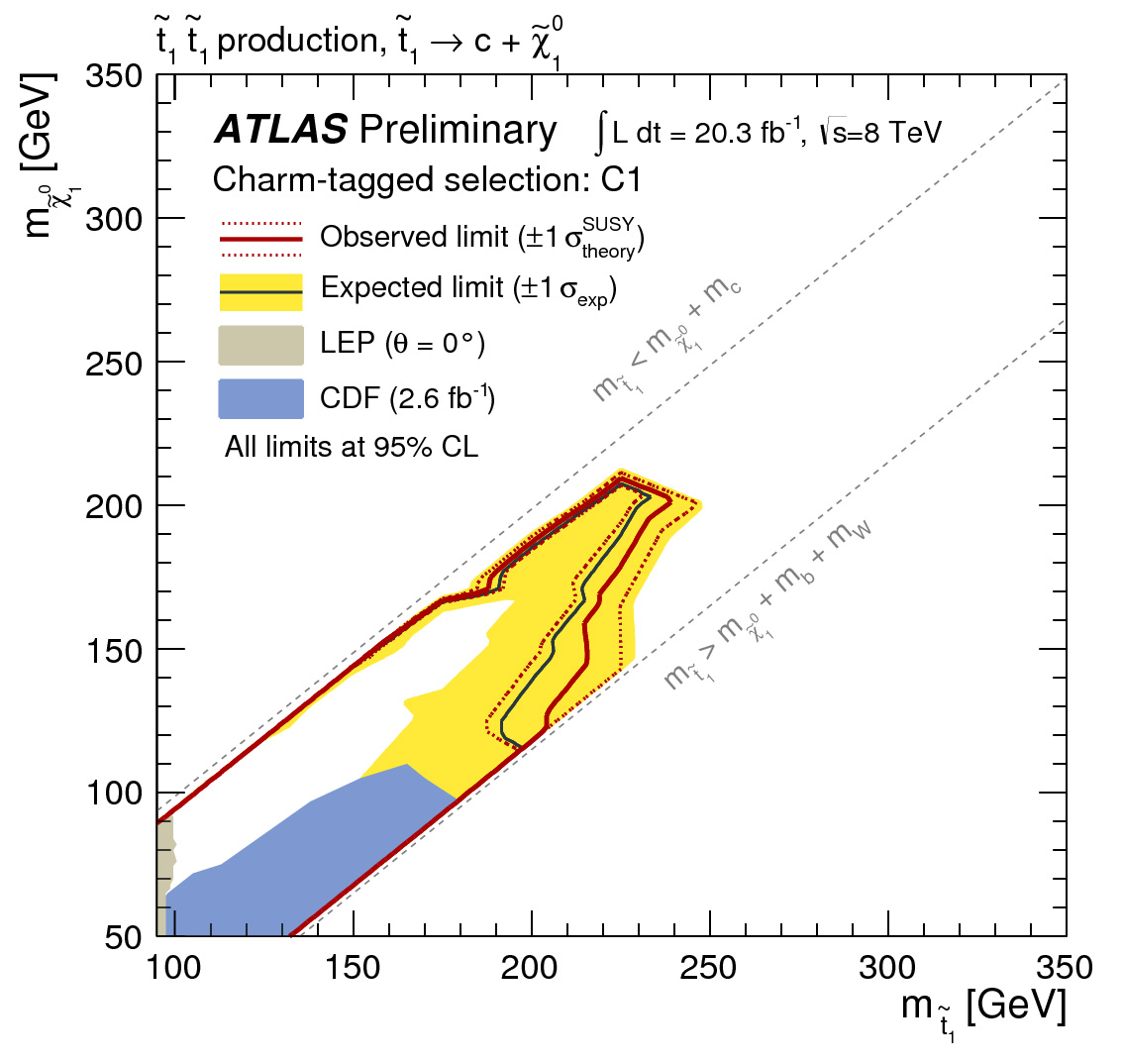
New searches for SUSY
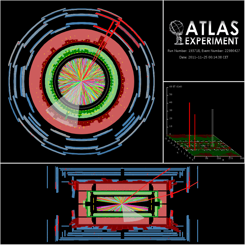
ATLAS today presented new searches for Supersymmetry, a theory that could explain the large amount of dark matter in the universe.
News |
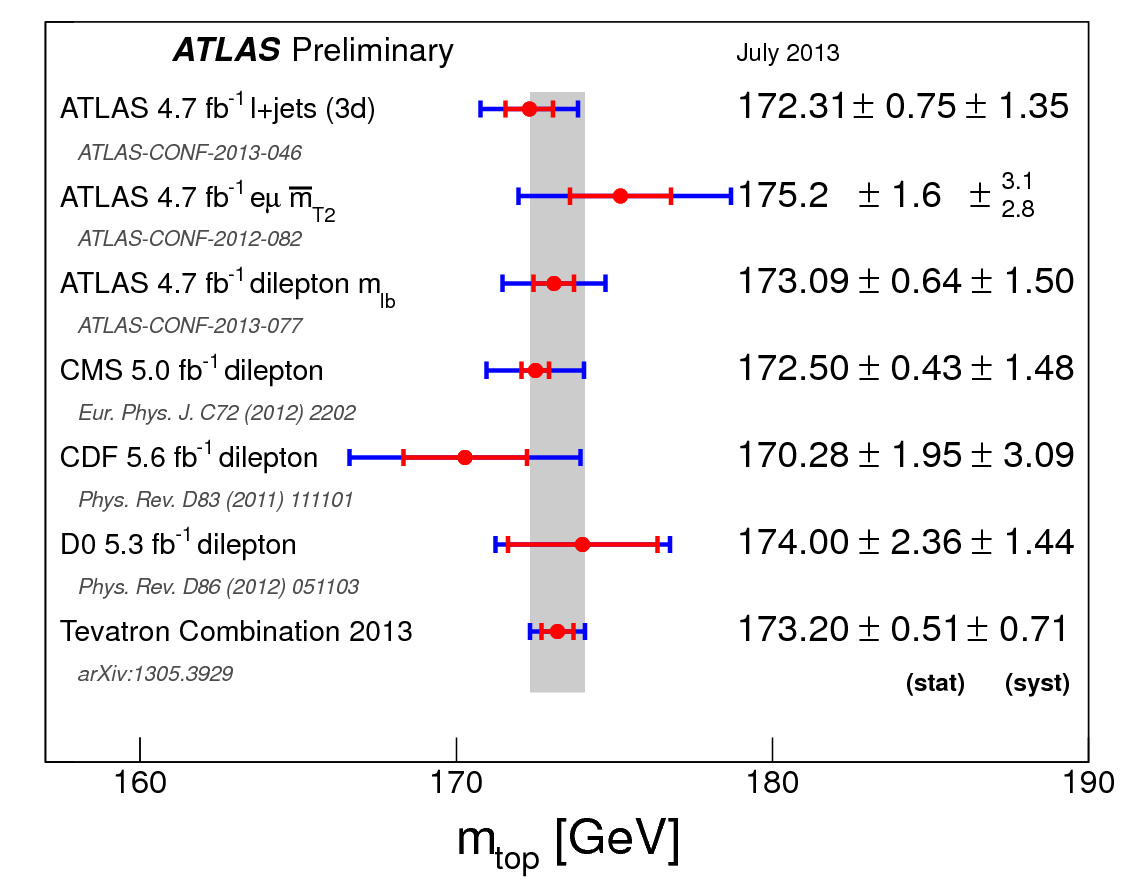
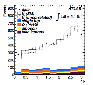
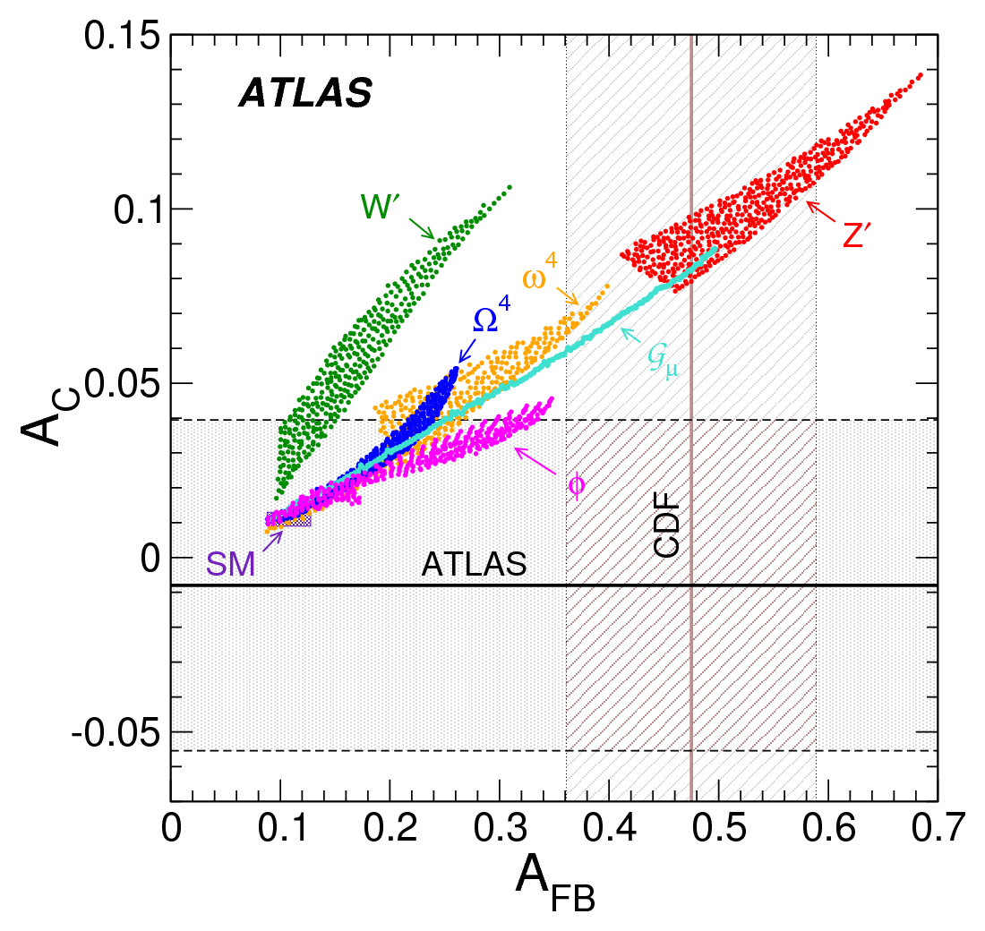
New results on the properties of the top quark
At the EPS HEP conference today, ATLAS released a new precise measurement of the top quark mass using events where both top quarks decay via W bosons to electrons or muons. ATLAS also presented limits on the possibility of the top quark decaying to channels not foreseen in the Standard Model. A comparison of the behaviour of top quarks and anti-top quarks produced at the LHC is in agreement with the prediction of the Standard Model, disfavouring models of new physics that require a large top/anti-top asymmetry.
News |

New Results for EPS
ATLAS physicists will be presenting new results at the biennial Europhysics conference on High Energy Physics this year. The conference, which will take place 18 to 24 July in Stockholm, Sweden, is organized by the High Energy and Particle Physics Division of the European Physical Society (EPS).
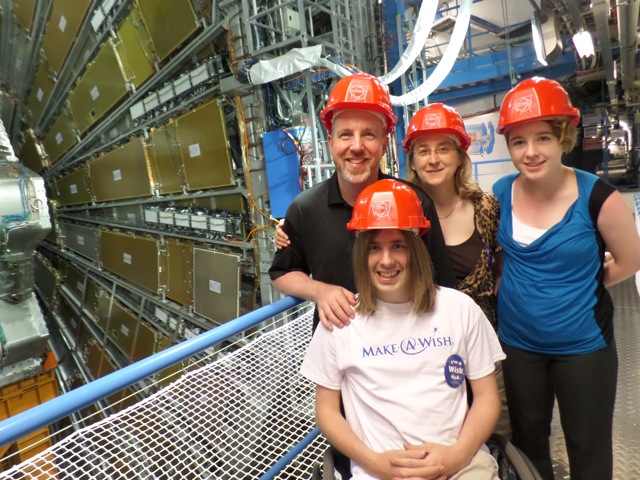
Granting a wish
Callum Kerr, 17, visited the ATLAS cavern on 8 July, with this family and a representative from Make-A-Wish Foundation.
News |

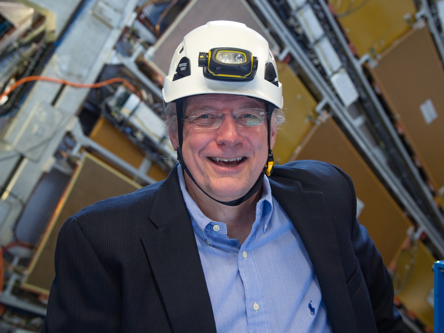
Everyone Here Is Motivated By Physics
In June 1993, ATLAS and CMS were given the provisional go-ahead to submit technical proposals. Twenty years later, for the discovery of the Higgs boson, the European Physical Society has awarded the High Energy and Particle Physics Prize 2013 to the research teams of the ATLAS and CMS experiments. For their “pioneering and outstanding leadership roles in the making” of the experiments, the prize also goes to ATLAS' Peter Jenni and CMS' Michel Della Negra and Tejinder Virdee. We talked to Peter Jenni, who was spokesperson of the ATLAS collaboration for the first 15 years, on ATLAS' past and future.
News |
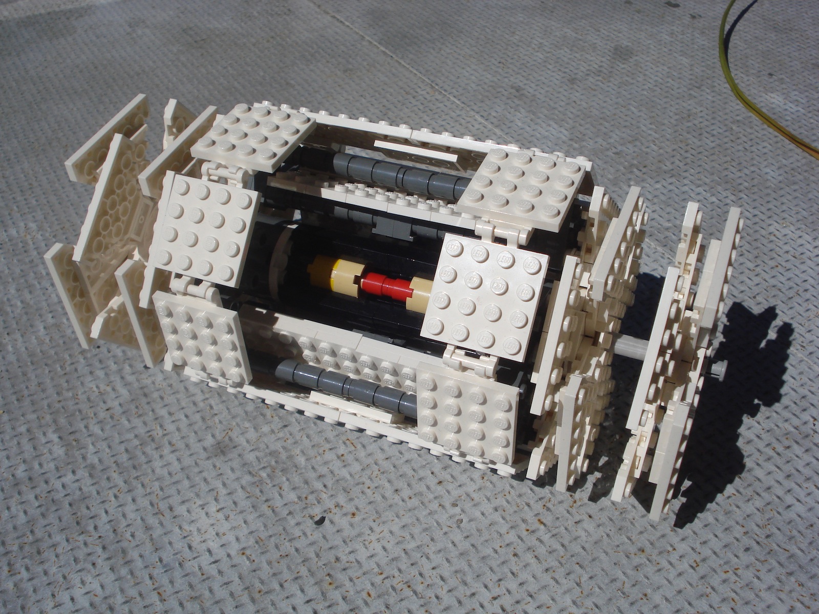
Want a small scale LEGO® version of the ATLAS detector?
A small scale version of the ATLAS detector can be made available as an official LEGO® product, but I need people to vote for it at LEGO Cuusoo. We need 10,000 votes to be considered by LEGO®.
Blog |
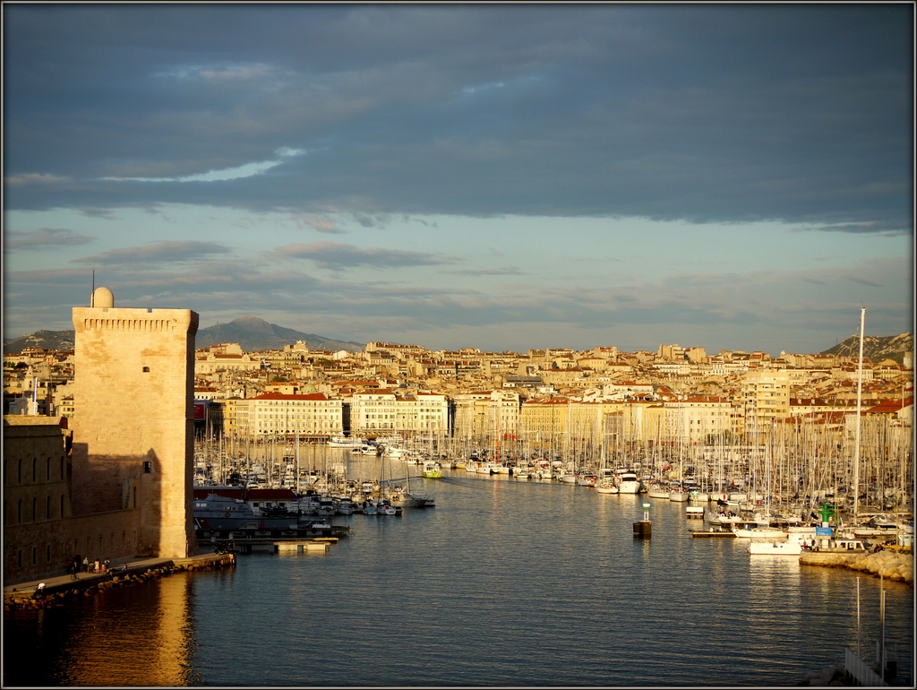
Report from DIS 2013
The series of workshops named "Deep Inelastic Scattering (DIS)" started way back in Durham, UK in 1993. In the last twenty years, particle physics has evolved in many ways, and this years DIS held at Marseille between April 22-26th was a testament to that fact. While it was one of the biggest conference in terms of Standard Model physics talks from ATLAS, it included talks and latest results covering the full ATLAS (and other big LHC experiments) physics program.
Blog |
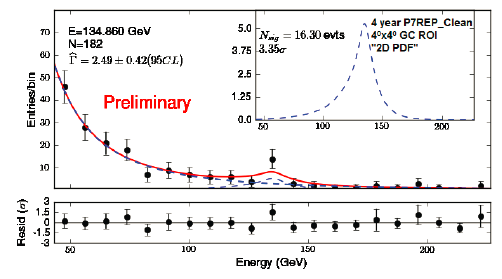
Moriond EW feedback
"Moriond", that's an important keyword in our collaboration. It's the winter deadline for many analyses, the occasion to see first results with the whole set of data collected in the past year. An important conference, one of the milestones of the year.
Blog |
What we learned from ATLAS at Les Rencontres de Moriond 2013
Les Rencontres de Moriond, an important conference for the worldwide community of particle physicists, took place from 2-16 March 2013 in La Thuile, Italy. Of all the scientists present, 22 ATLAS physicists had been invited to reveal the experiment's latest findings. What did we learn from this new ATLAS physics harvest?
News |
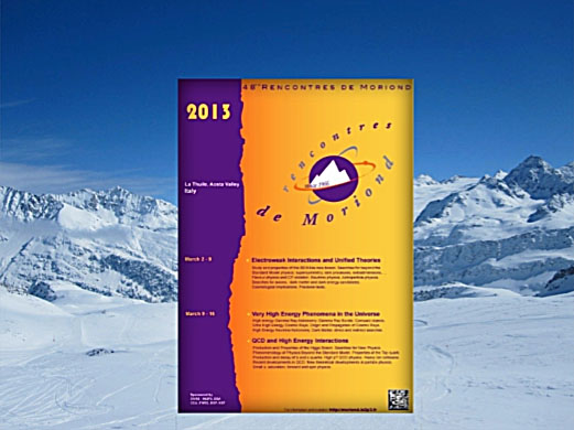
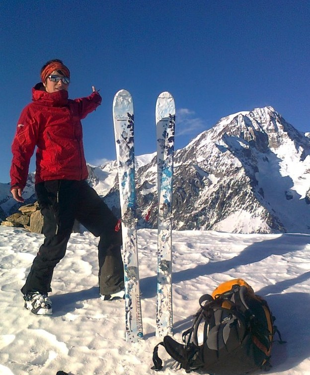
ATLAS in the Italian Alps for the Rencontres de Moriond 2013
From March 2nd to March 16th 2013 the mythic "Rencontres de Moriond" is taking place in the Italian Alps at the La Tuile ski resort. For the 48th edition of this famous event, more than 420 physicists, theorists and experimentalists, young and more experienced, coming from the four corners of the planet get together in this pleasant environment to share their most recent results and ideas on particle physics. Twenty-two ATLAS physicists were invited to divulge the latest findings of the ATLAS Experiment.
News |

2012: A Year for Science – A Year for Discovery
Amazing, incredible, emotional. These are uncommon words for summarizing the annual accomplishments of a particle physics experiment. Yet 2012 has been a fantastically uncommon year for ATLAS, one of the main experiments at CERN: marvellous machine performance, numerous and interesting physics results, plenty of interactions with students and general public, and - last but not least - a major discovery!
News |
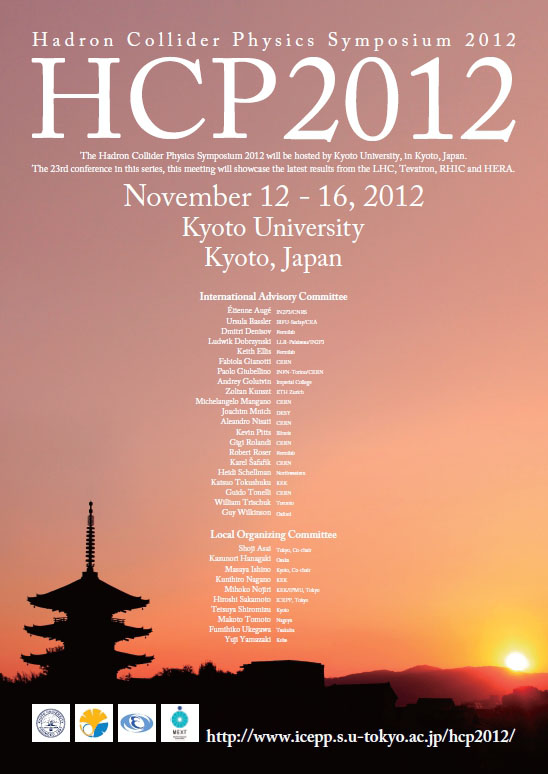
ATLAS in the Land of the Rising Sun for HCP 2012
From November 12th to November 16th, more than 250 particle physicists are gathering in Kyoto, Japan to share their latest results. One of the key international particle physics conferences of the year, the Hadron Collider Physics Symposium 2012 (HCP 2012), will take place this year in the Land of the Rising Sun.
News |
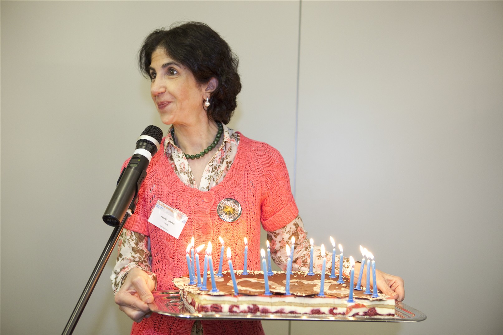
Happy Birthday ATLAS!
Twenty years ago the name “ATLAS” was first used on an official document, the Letter of Intent, to refer to the detector which has been taking data for nigh on three years now, including those data on which the recent Higgs results were based. It has been two decades of growth, development and hard work, resulting in this year’s observation of a Higgs-like particle. All the more reason for the experiment to take a few moments to look back and celebrate.
News |
TOP 2012 - Part 2
Welcome back, dedicated top quark enthusiast. I’m sure you’ve all been waiting on the edge of your seats for an update from TOP 2012, and I can now confirm that a combined team of LHC & Tevatron physicists narrowly beat a mixed team of physicists from LHC & Tevatron at croquet.
Blog |
TOP 2012 - Part 1
Greetings from the TOP 2012 conference, Winchester UK! What’s a ‘Winchester’ I hear you asking? A type of gun? Indeed yes, though sadly not of the smoking variety that we’re all so keen to find. However in this particular case Winchester is a historical town in the south of England, complete with the typical rolling green fields, a cathedral, and the not so typical contingent of visiting physicists!
Blog |
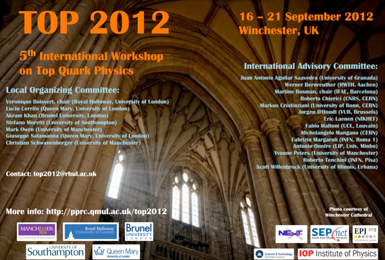
The Physics of Top Quarks
The 5th International Workshop on Top Quark Physics (TOP2012) will take place in Winchester, UK, from the 16th to the 21st of September. It will gather experts in the field of top quark physics as well as PhD students and will highlight the newest results and topics related to the physics of top quarks.
News |
What should we know about the Higgs particle?
On the 4th of July, CERN announced the discovery of a new particle that can be interpreted as the Higgs boson with both the ATLAS and CMS experiments. Since this is one of the most important discoveries over the last 10 or 20 years in particle physics, let’s have a look to the full story.
Blog |
ATLAS Heavy Ion Results Presented at QM 2012 in Washington, D.C.
The Quark Matter conference, which takes place every two years, is this year being organised in Washington, DC, USA on 13-18 August 2012 (QM2012). It will bring together both experimentalists and theorists from all over the world who are studying heavy ion physics at ultra high energies.
News |
ATLAS Supersymmetry Searches and More at SUSY 2012 in Beijing
The 20th International Conference on Supersymmetry and Unification of Fundamental Interactions (SUSY 2012) is taking place in Beijing, China on 13 -18 August 2012. SUSY is the theory which, if confirmed by experiment, will be the high energy extension of the Standard Model (SM). In SUSY, every particle should have a massive "shadow" particle or super-partner. Experimentalists have been looking for years for proof of the existence of these SUSY particles or sparticles.
News |
Family Name
Hoecker
Given Name
Andreas
Family Name
Charlton
Given Name
David
Family Name
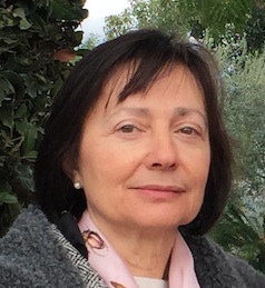
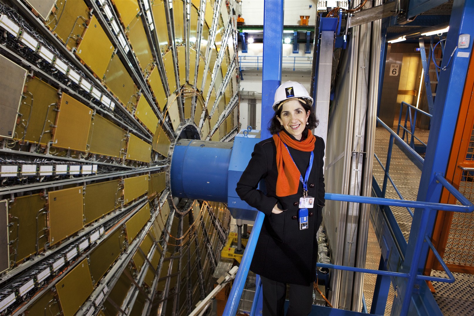
Gianotti
Given Name
Fabiola
Family Name
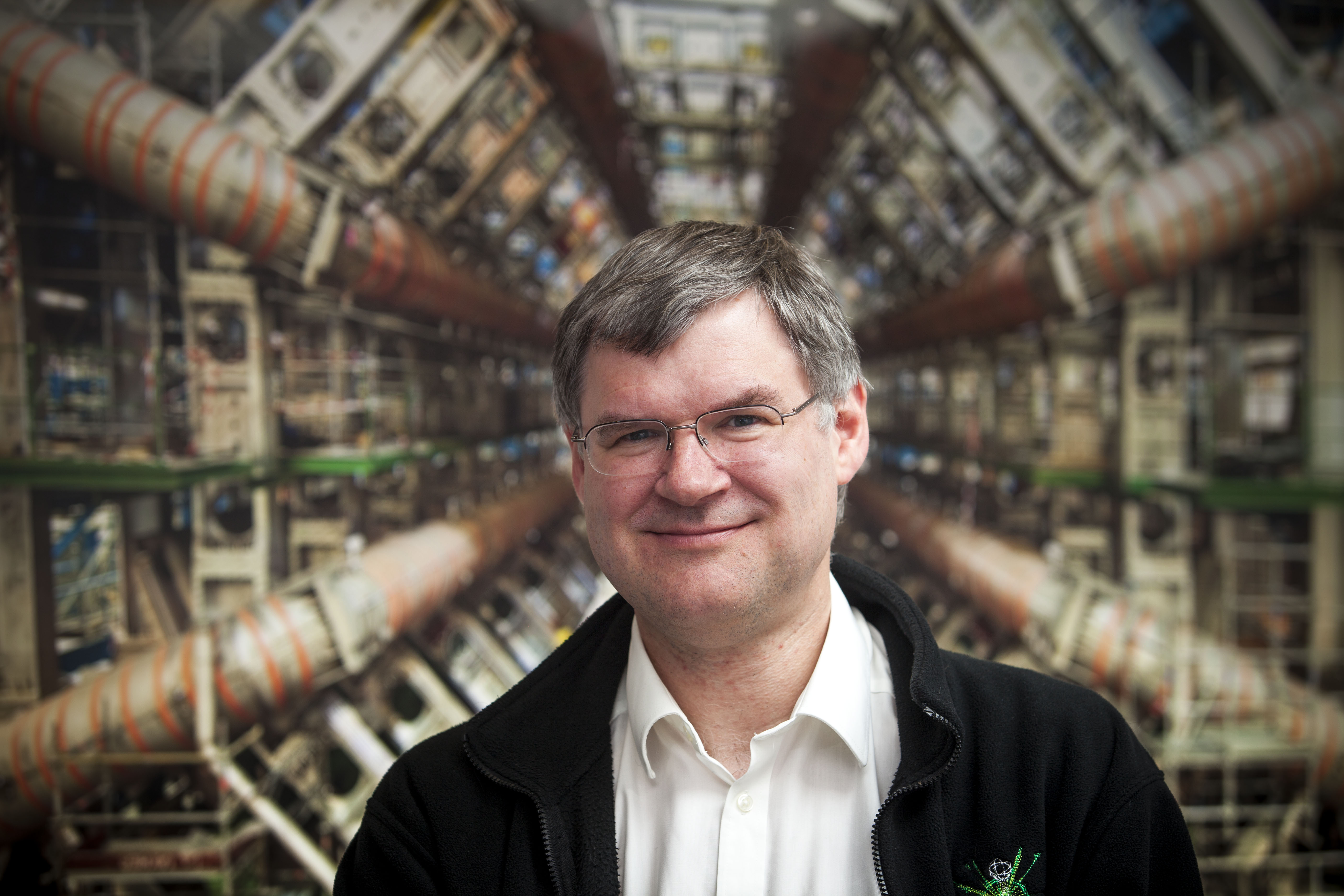
Jenni
Given Name
Peter
Family Name
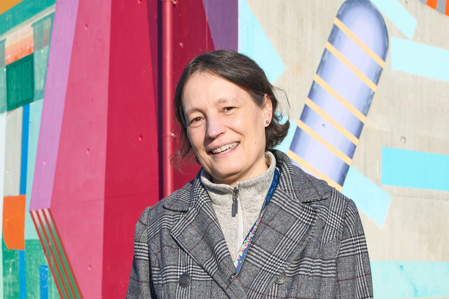
Vincter
Given Name
Manuella
Family Name
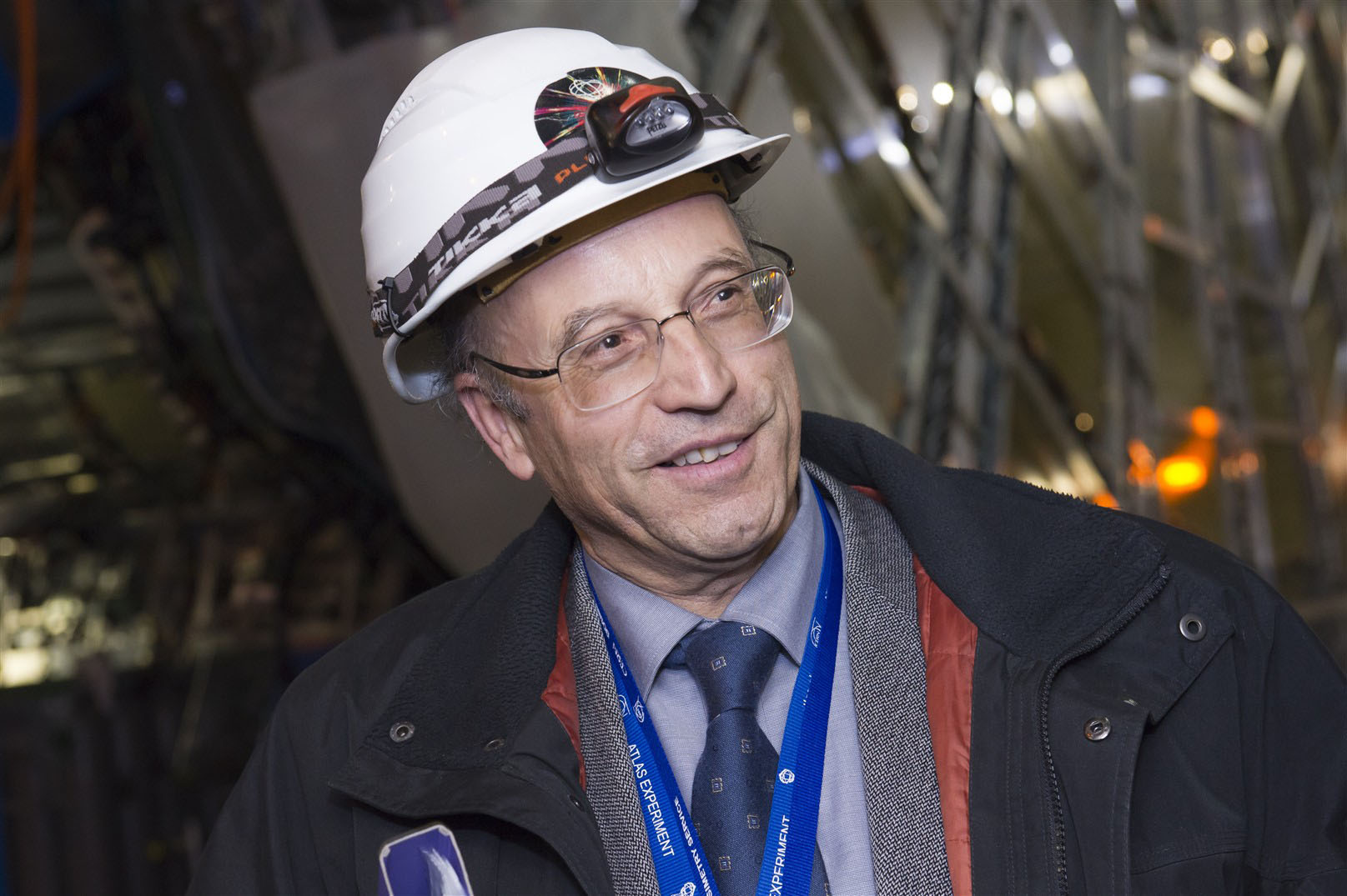
Lanni
Given Name
Francesco
Family Name
Pontecorvo
Given Name
Ludovico
Family Name
Francis
Given Name
David